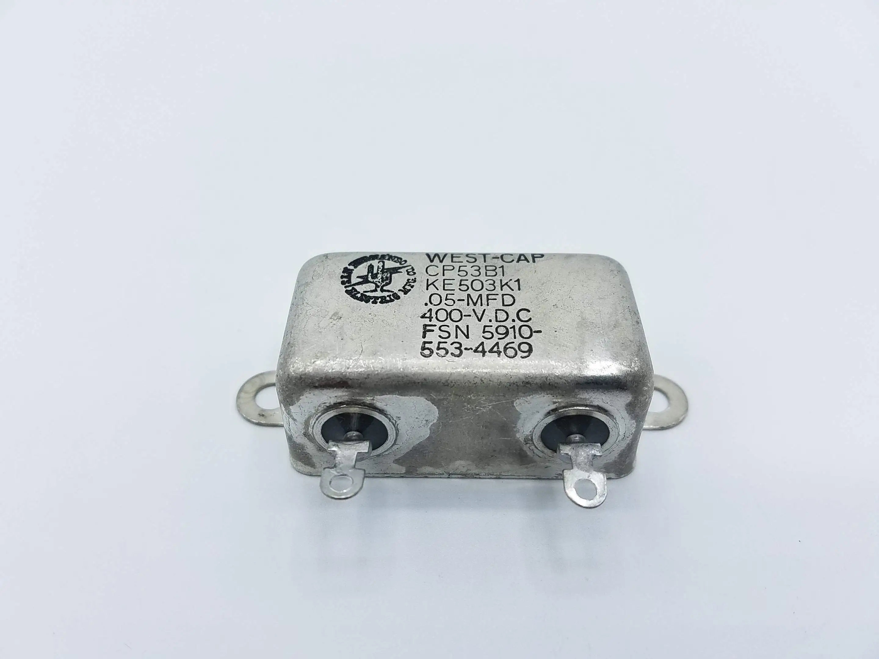
Paper Dielectric Fixed Capacitor
CP53B1KE503K1

W/mtg tabs/flanges, terminal(s) on one surface body style, not established reliability indicator, 0.812 inches nominal body length, 1.000 inches nominal body width, 0.750 inches nominal body height, 0.188 inches nominal unthreaded mounting hole diameter
| DAC | HCC | DMIL | RNCC |
|---|---|---|---|
| 6 | - | - | C |
| RNVC | SADC | MSDS | RNAAC |
|---|---|---|---|
| 1 | AC | - | ZZ |
A capacitor whose capacitance value cannot be adjusted or varied, having paper as the dielectric material. It may be a single unit or consist of two or more fixed units which cannot be seperated. For items whose dielectric material consist of plasticized (plastic impregnated) paper or paper-plastic combinations, see capacitor, fixed, plastic dielectric. For items whose electrodes consist of a metallic film deposited (metallized) on the dielectric material, see capacitor, fixed, metalized, paper-plastic dielectric.
| INC | FIIG | Concept | Condition |
|---|---|---|---|
| 00003 | A010B0 | 1 | 1 |
Details
The style designation indicating the configuration that most nearly corresponds to the appearance of the body.Details
An indication that the level of probability that an item will operate without failure,at a specified rated capability,at a specified temperature,and for a specified period of time,has been established by testing random samples of production lot.Details
A measurement of the longest dimension of the body,in distinction from width.Details
A measurement taken at right angles to the length of the body,in distinction from thickness.Details
A measurement from the bottom to the top of the body,in distinction from depth.Details
The length of a straight line which passes through the center of an unthreaded mounting hole,and terminates at the circumference.Details
The distance between centerlines of mounting facilities parallel to the length of the item.Details
A designator indicating a graphic representation,in standard and accepted symbols,of essential electrical-electronic elements and related connections on the item.Details
Indicates the type and number of facilities by which the item is mounted.Details
Those features,not otherwise specified,which may be required for proper functioning of the item.Details
Direct current resistance between two conductors that are separated by an insulating material,measured at the maximum operating temperature of the item.Details
The relative level of the quantity of electric charge at a given potential which the capacitor is capable of receiving and storing per section.Details
The temperature/s/ at which an item can function without voltage derating.Details
The highest value and type of potential that may be continuously applied to the item per section at the highest operating temperature permissible without voltage derating.Details
The limits of permissible deviation per section of a measured value from a specified value.Details
The chemical compound or mechanical mixture properties of which the case is fabricated. please use mrc matt with isac table 0326 in place of this canceled mrc.Details
Direct current resistance between two conductors that are separated by an insulating material,measured at reference temperature.Details
The ratio of resistance to capacitive reactance measured at reference temperature.Details
The metallic,nonmetallic,and/or chemical properties with which the item is plated,dipped,and/or coated. the treatment is designed to protect the terminal surface(s) and cannot be wiped off.Details
The specification,standard,drawing,or similar instrument that specifies environmental and performance requirements or test conditions under which an item is tested and establishes acceptable limits within which the item must conform identified by an alphabetic and/or numeric reference number. includes the commercial and government entity (cage) code of the entity controlling the instrument.Details
Indicates the type and number of terminals for providing electrical connection.| Part | CAGE | DAC | HCC | RNCC | RNVC | MSDS | RNAAC |
|---|---|---|---|---|---|---|---|
| CP53B1KE503K1 | 81349 | E | - | 2 | 2 | - | XX |
| MIL-C-25/4 | 81349 | E | - | 4 | 1 | - | ZZ |
| MILC25 | 81349 | E | - | 5 | 9 | - | XX |
| HMIC | PMIC | ESD/EMI | Criticality |
|---|---|---|---|
| P | U | - | - |
| UFC | HMC | LTL | LCL |
|---|---|---|---|
| 34450 | - | P | - |
| RVC | WCC | TCC | SHC |
|---|---|---|---|
| - | 72D | Z | 9 |
Provided with every order
Order with confidence, we are a valued certified supplier serving customers in the military and aerospace industries.
- Counterfeit Parts Prevention
- 100% Product Inspections
- 7 Year Record Retention
- On Time Delivery
- HAZMAT Certified
- Worldwide Shipping
What is the NIIN of the NSN 5910-00-553-4469?
When the NSN 5910-00-553-4469 was assigned to the Federal Catalog?
Does the NSN 5910-00-553-4469 contain any precious metals?
Does the NSN 5910-00-553-4469 contain any hazardous material?
Can't Find It
If you didn't find what you need, don't worry, we're here to help! Our team is ready to help you find exactly what you need. Click below to contact us.
